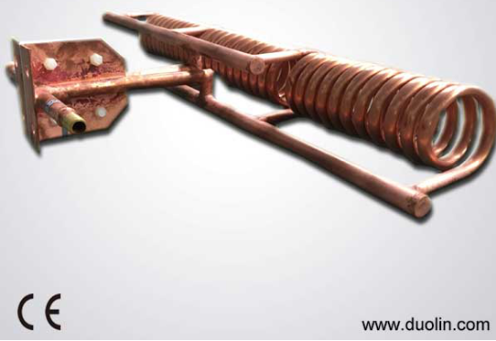
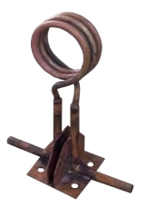
The heating effect of the workpiece not only depends on the power of the power supply, but also with the shape of the induction coil, the number of turns, the length of the copper tube, the workpiece material.

Shape and other factors are directly related to the equipment to get the most efficient use of power. Depending on the heating material and shape, design suitable heating coil is very important
The design of the induction loop should generally follow the following principles:
1, first determine the heating purpose, quenching, forging or hot forming and so on.
2, according to process requirements to determine the basic shape of the coil: round, rectangular, pan incense, irregular
In General, round, square workpiece, heating coil should be round or rectangular-based.
The welding process of the coil according to the workpiece part of the shape of the design, the coil should be welded to the two kinds of workpiece at the same time heating.
3, Copper used
In general, SSF-60-160 should be selected as ≥φ8mm copper tube or the corresponding area of the rectangular tube
SSF ~ 50 should be selected ≥ φ5 copper tube or the corresponding area of the rectangular tube
HFP ~ 20 should be selected ≥ φ3 copper tube or corresponding Area of the tube.
MFP series of equipment should be based on the work of equipment to determine the specific material.
4, the gap between the coil and the workpiece
Usually the heat transfer process should be based on the workpiece size, coil diameter and workpiece spacing should be controlled at 4 ~ 20mm; size bigger, the gap bigger
Usually the quenching process should be based on the quenching depth of the workpiece, the coil diameter and workpiece spacing should be controlled in the 1.5 ~ 10mm; deeper depth,gap bigger
5, the inductance of the coil
In general, the inductance of the company's ultrasonic equipment sensor should be controlled in the following range (the following data are data with no load)
SSF-30 ~ 50 equipment:0.7 ~ 1μH (transformer secondary single turn situation), primary total inductance (180-256μH);
SSF-60 equipment:0.8 ~ 1μH (transformer secondary single turn situation)primary total inductance (135-169μH);
SSF-80 equipment0.8 ~ 1μH (transformer secondary single turn situation)primary total inductance (115-144μH);
SSF-120 equipment0.8 ~ 1μH (transformer secondary single turn situation)primary total inductance (80-100μH);
SSF-160 equipment3.5 ~ 4μH (secondary secondary transformer case)primary total inductance (88-100μH);
HFP-20 equipment:0.5 ~ 0.8μH (transformer secondary single turn situation),primary total inductance (200-320μH);
The secondary resonant device and the adjustable ratio machine can be used to determine the inductance parameter according to the configuration of the device.
6, the use of magnetic
Usually the quenching sensor can be added to the magnet, the material is copper, stainless steel and other magnetic metal can be added when the magnet can be added
SSF, HFP, HGP and other high-frequency equipment should be selected ferrite material magnet. MFP equipment should be selected silicon steel sheet as a magnetic

Post time: Feb-04-2021


