Written by Mr. Zeng xiaolin from CHENGDU DUOLIN ELECTRIC CO., LTD
This article analyzes the disadvantages of current SCR MF Induction Heating System and introduces a new type of MF Induction Heating System for forging with IGBT power devices. It is Series Resonant Circuit with features of significant energy-saving effect and can be easily launched at any load conditions.
At present, most manufacturers use LC Parallel Resonant Circuit and SCR as inverter for their MF Induction Heating System. Such SCR inverter technology was developed early 70s of last century. Please see Diagram 1!
Ⅰ. SCR LC Parallel Resonant Circuit
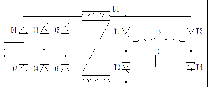
Diagram 1
In this type circuit, Rectifying section performs two tasks:
1. To convert AC current into DC current by six SCRs(silicon controlled rectifier).
2. To adjust power of machine.
The disadvantage of this circuit:
1. Additional investment in Power Factor Compensation Capacitor Cabinet (PFCCC).
Power adjustment is achieved by adjusting the conduction angle of SCR, and reducing of the conduction angle will lower the power factor of power grid. So users have to buy Power Factor Compensation Capacitor Cabinet. And then cost is increased.
2. Low power factor
The power factor is only 0.8 to 0.85 in inverter section due to turn-off property of SCR.
3. High energy consumption
l After rectification, DC filtering is done by large DC reactor. Thus 1%-3% energy loss is generated in this section.
l Inverter circuit is fulfilled by the four Thyristors(SCR), so about 5% energy loss is generated at inverter section.
l Output section is parallel resonant circuit which is made up of induction coil and capacitor. Limited by breakdown voltage of SCR, voltage output ≤750V. Oscillation current at induction coil is Q (5 to 10) times of DC current (Q is quality factor of resonant circuit.). Thus there is much energy loss at induction coil. So with parallel resonant circuit, the energy loss is approximately 25% to 30% of machine power.
Therefore the efficiency of SCR MF Induction Heating System is approximately 60% to 70%.
Clearly, raise the voltage on the induction coil and lower the oscillation circuit value Q which can improve the efficiency of machine. But in parallel resonant circuit, both ends of induction coil directly connected to thyristor, if raise the voltage of induction coil, the breakdown voltage of thyristors must be raised. Therefore to raise breakdown voltage of thyristors will increase manufacturing costs but also constrained by breakdown voltage of thyristor.
Thyristor is a semi-controlled type power device, when the oscillation circuit value Q <10, easy to stop oscillation or failure of oscillation.
People used SCR MF Induction heating system know the truth if heating station filled cold material; it is difficult to start oscillation. So in order to improve the efficiency of MF Induction heating system must seek another power device and another circuit: IGBT and LC Series Resonant Circuit. Please see Diagram 2 below!
Ⅱ. IGBT LC Series Resonant Circuit
—–used in Duolin MF Induction Heating System
In early 90s, a new power device IGBT was born with features of high power, low switch loss and high working frequency up to 100 kHz. IGBT technology is quite mature after 20 years of development, especially the fourth generation IGBT made by INFINEON. Its saturation voltage is ≤ 1.7 while the Hard-switching frequency has reached 20KHZ. IGBT is absolute dominance in fields such as frequency inverter, switching power supply and induction heating.
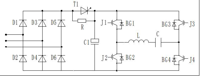
Diagram 2
In this circuit, rectifying is done directly by six (6) diodes without chopping so there is minimized impact on power factor of grid. In the series resonant circuit, filtering job is done by a capacitor C1 instead of the large and heavy reactor to achieve energy saving. SCR T1 here works as a switch only. When the capacitor is charged to a certain voltage, the SCR T1 is connected.
Inverter section comprises four (4) IGBTs. IGBT’s conduction loss is equal to SCR’s but IGBT’s switch loss is lower than SCR’s so loss of inverter current is low, about3%.
There are two ways of power adjustment: 1. by changing working frequency of inverter section; 2. by changing conducting time of IGBT.
The output section is Series Resonant Circuit which is made up by inductor (L) and capacitor (C). Characteristic of this circuit is that the current through IGBT equal to the current through inductor and capacitor but the voltage at inductor is 3-10 (Q value) times of rectified DC voltage. Voltage at inductor (L) is offered directly by capacitor (C), so there is no need to raise breakdown voltage of power devices (IGBT) when raising voltage at inductor.
Power at inductor P = V(voltage at inductor) × I (current through inductor).Now let’s compare the loss at inductor between Parallel and Series resonant circuit. Assume the power at inductor is P.
Parallel Resonant Circuit (prc): P=Vprc × Iprc; P=750 × Iprc; Iprc=P/750
Series Resonant Circuit (src): P=Vsrc × Isrc; P=1500 × Isrc; Isrc=P/1500 (minimum Vsrc = 3 × 500 DC Vol)
Thus Isrc = 1/2 I prc; we know the loss of inductor is only related to resistance of inductor. The resistance is assumed R, then the power loss is:
P = I2R; Pprc = Iprc2R; Psrc = Isrc2 R = (1/2 Iprc)2 R = 1/4 Iprc2 R
Advantages of this circuit or Duolin’s MF induction heating system:
1. High efficiency
Therefore under condition of same power and same inductor, maximum loss of Series Resonant inductor is a quarter (1/4) of Parallel Resonant inductor (Please see above formula!). Then loss of series resonant output section is approximately 5% – 10% of machine power, so efficiency of MF Induction Heating System used Series Resonant Circuit is 80% – 90%.
2. Low energy consumption
In the Series Resonant Circuit, voltage at inductor is not related to breakdown voltage of power device. So as long as inductor insulation allowed, to raise voltage at inductor can reduce inductor loss, further improve machine efficiency. The principle is as same as power transmission of grid in high voltage.
Therefore, when designing, select a right Q value that can guarantee the reliability of machine as well as improve machine efficiency, and then can significantly save energy 10% -30% compared with conventional thyristor (SCR) induction heating system.
3. High power factor
Normally MF Induction Heating System with IGBT Series Resonant Circuit has high power factor above 0.95. If rectifying with 12-pulse, power factor can be up to 0.98.
4. Easy to launch at any load condition
IGBT is a full-controlled power device. Turn-on/off of IGBT is controlled directly by gate without any relation to power factor and Q value of oscillation circuit. So machine can be easily launched at any load condition.
Anyway MF Induction Heating System with IGBT Series Resonant Circuit is best choice of forging companies.
Post time: Feb-04-2021


